Dynamic Tonality
Power Transformer Design This Section covers the design of power trans-formers used in buck-derived topologies: forward converter, bridge, half-bridge, and full-wave center-tap. Flyback transformers (actually coupled induc-tors) are covered in a later Section. For more spe-cialized applications, the principles discussed herein will generally.
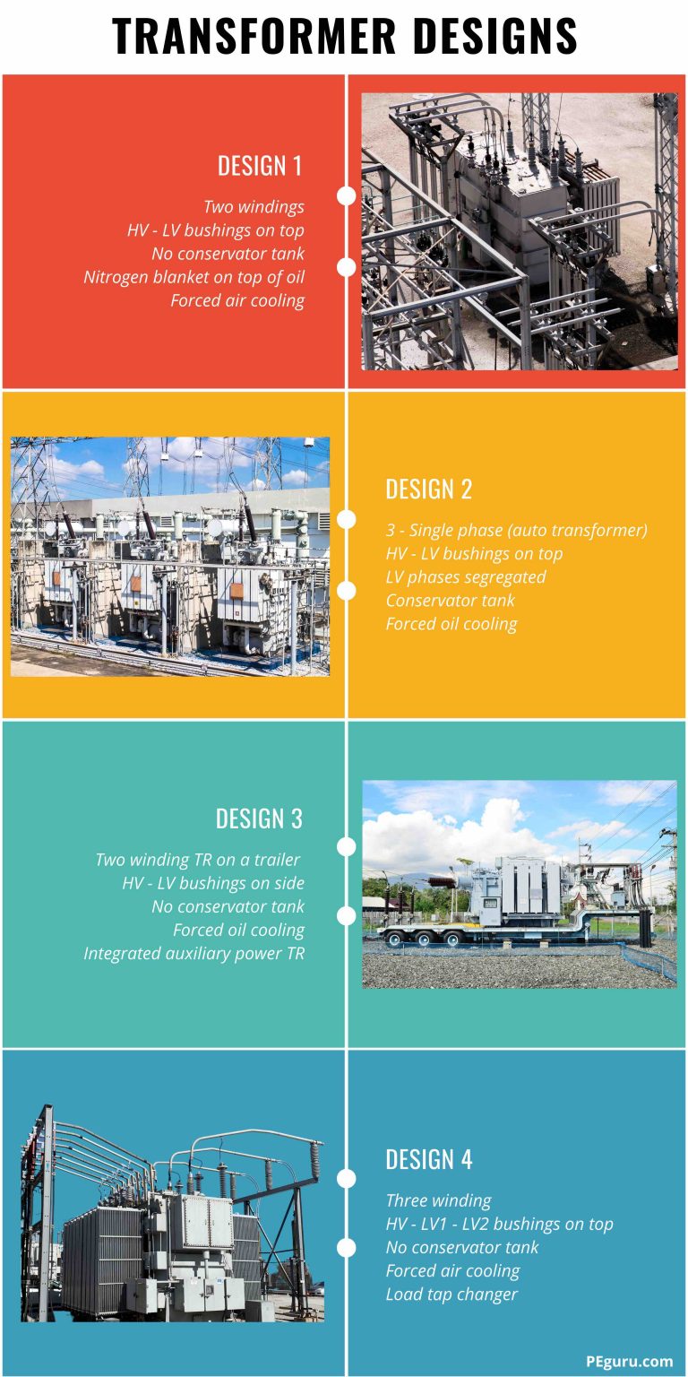
Power Transformers Design and Application PEguru
For example, if this transformer happens to have an impedance of 5.5%, it means the secondary (output) voltage will sag 5.5% below 24 VAC at full load, assuming the primary voltage is maintained at the standard 120 VAC level. 5.5% of 24 volts is 1.32 volts, and so this transformer's secondary voltage will "sag" from 24 volts down to 22.68.
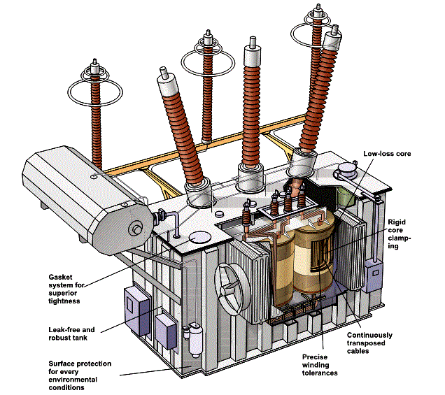
Transformer Theory of Operation Inst Tools
Basics of Transformer Design kkazem 9 Dec 2021 I decided to write a Blog on the basics of transformer design as I believe there are a lot of members that may not have been exposed to it before. Some think it's a black art or black magic, but it's actually based on rock solid science.
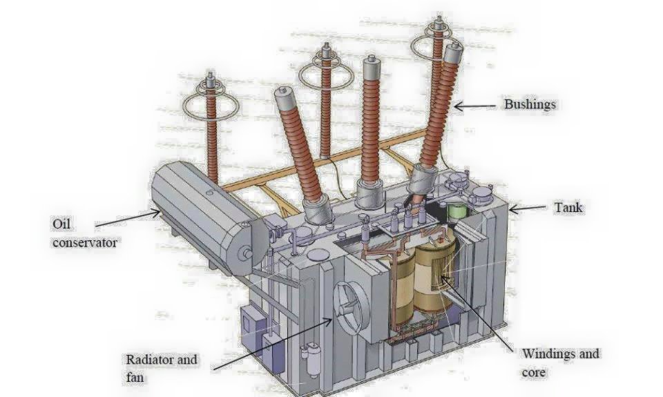
Power Transformer Showing Electrical Engineering Books
How to Design a Transformer: Size and Selection September 27, 2022 by Simon Mugo Transformers are key electrical components useful in determining the power reaching the load from the supply. In this article, you will learn how to design a transformer through a well-documented guide that will enable you to select and size transformers.
Business Intelligence and Data Warehousing Notes Enable BASIC transformer in DataStage
1 Power transformer design 1.1 Initial calculations 1.2 Type of iron (electrical steel) 1.3 Secondary turns calculation 1.4 Thickness of coil windings 1.5 Insulation 2 Wire selection 3 The core stack 3.1 Stacking Factor 3.2 Scrapless Laminations 3.3 Core Stack Assembly 4 Watts versus volt-amperes 5 Rectifier transformers 6 Equations

Power Transformer Electrical Academia
Fundamentals of transformer design By H du Preez, Consultant A transformer is a static piece of equipment with a complicated electromagnetic circuit. The electrical energy is transferred from one electrical circuit to another through a magnetic field. In its simplest form, a transformer consists of two conducting coils having a mutual inductance.
Transformers 3 designs
612 Pages by CRC Press Description In the newest edition, the reader will learn the basics of transformer design, starting from fundamental principles and ending with advanced model simulations.

Transformer Design, 230 V to 12 V Step Down Transformer, Materials
Power Transformer Design Step No. 2 Calculate the electrical conditions, Ke Kf = 4.44, [sine wave] Ke = 0.145(4.44)2 (47 )2 (1.6)2 (lO 4) * =1.62 Step No. 3 Calculate the core geometry, Kg. *•-•£? [cm'] ^=31.7, [cm5] Step No. 4 Select a lamination from Chapter 3, comparable in core geometry, Kg.

Transformer Design, 230 V to 12 V Step Down Transformer, Materials
The two most common and basic designs of transformer construction are the Closed-core Transformer and the Shell-core Transformer. In the "closed-core" type (core form) transformer, the primary and secondary windings are wound outside and surround the core ring.

Electrical Engineering World Transformer Parts Electrical engineering books, Power
1 Overview Transformer Design Transformer Types Construction and Parts Core & Coils Electrical design Losses & Impedance Thermal, Dielectric & Short Circuit Cooling & Sound Level Mechanical design Tank Oil Preservation Transformer Manufacturing Process Power Transmission & Distribution

List of the transformer model parameters. Download Table
Basic Transformer Theory The above figure represents the essential elements for a transformer: a magnetic core with a primary and secondary coil wound on the limbs of the magnetic core. An alternating voltage (Vp) applied to the primary creates an alternating current (Ip) through the primary.

multiple choice questions on transformer 14 Electrical Engineering
April 9, 2023 by Andrew Strohm A transformer transfers power from one circuit to another without any change in frequency. There are two types of windings in a transformer, one is primary winding and the other is secondary winding.
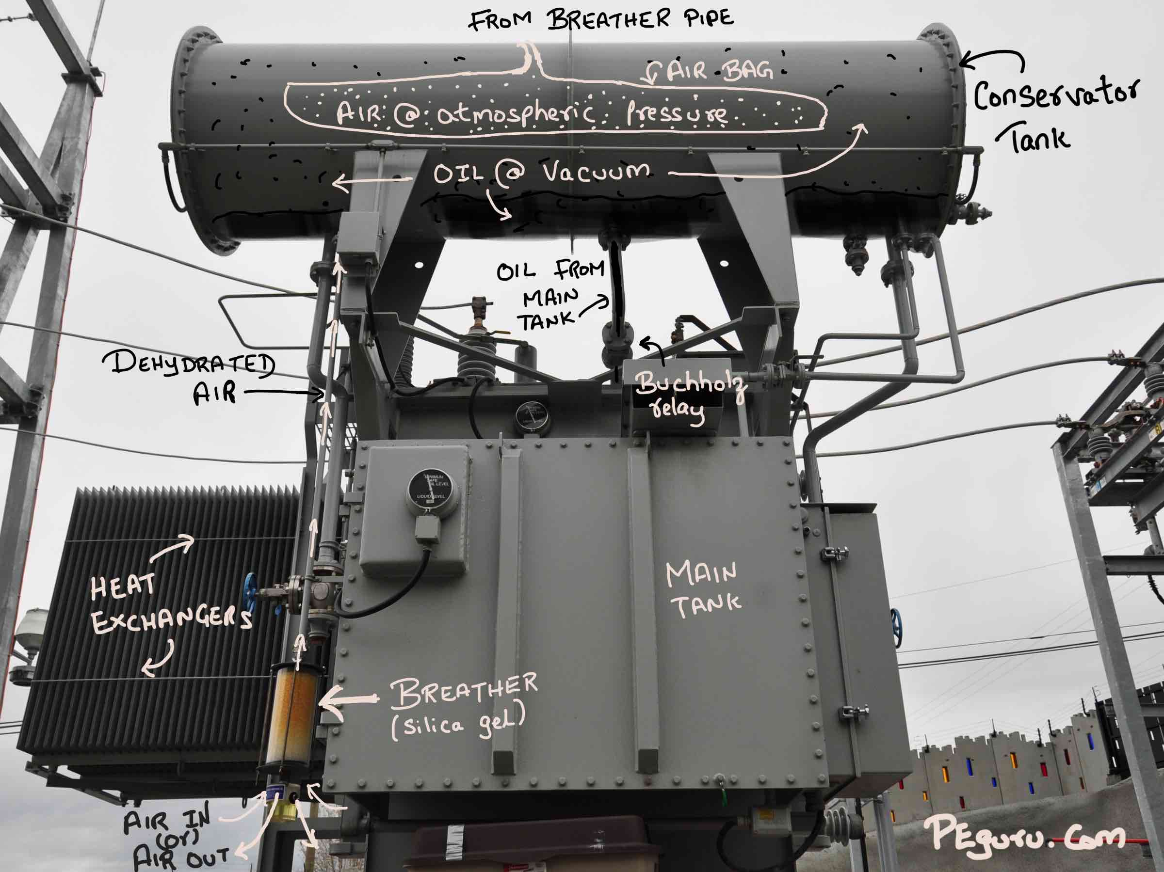
Power Transformers Design and Application PEguru
Basics of Transformer Published February 22, 2018 0 E Emmanuel Odunlade Author TRANSFORMERS Transformers generally, are devices capable of converting quantities from one value to the other.

Transformer design part I YouTube
Connect one probe at one end of one of the wires and the other probe to the opposite end of the same wire. The resistance should be very low. Repeat for the second wire. Step 6: If either resistance measurements from steps 4 or 5 indicate a problem, the winding (s) must be re-made. Step 7: Power the primary winding of the transformer (you can.

Transformer Free Stock Photo Public Domain Pictures
A basic transformer consists of two coils that are electrically separate and inductive, but are magnetically linked through a path of reluctance. The working principle of the transformer can be understood from the figure below. Transformer Working As shown above the electrical transformer has primary and secondary windings.
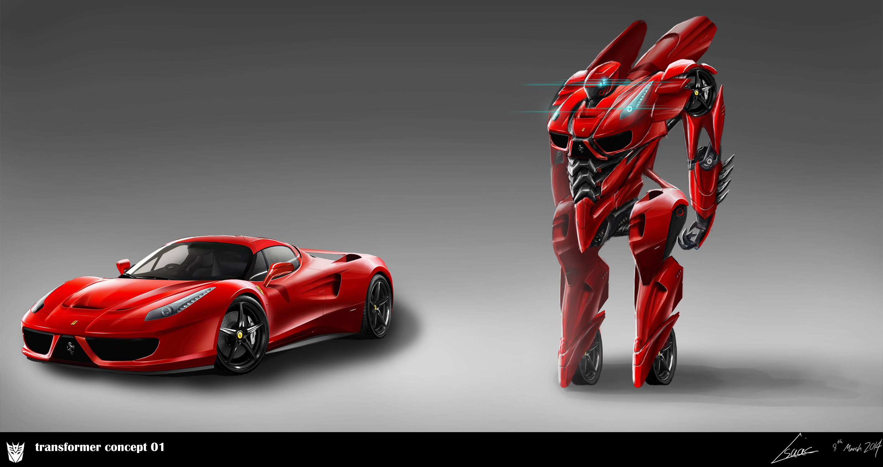
transformer concept 01 by nobody00000000 on DeviantArt
A transformer basically is very simple static (or stationary) electro-magnetic passive electrical device that works on the principle of Faraday's law of induction by converting electrical energy from one value to another.