circuit diagram of inverter air conditioner Wiring Diagram
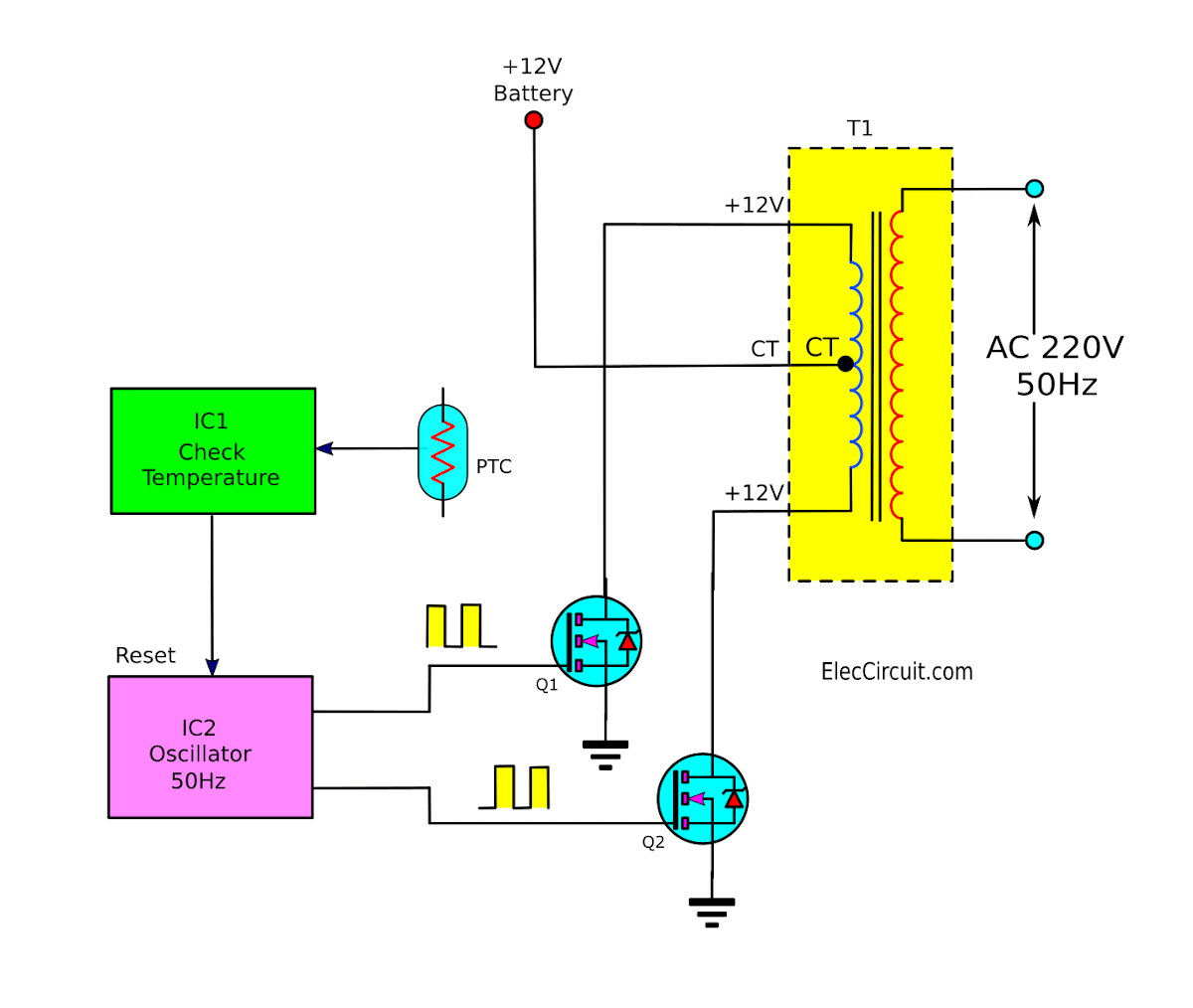
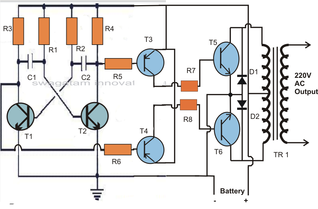
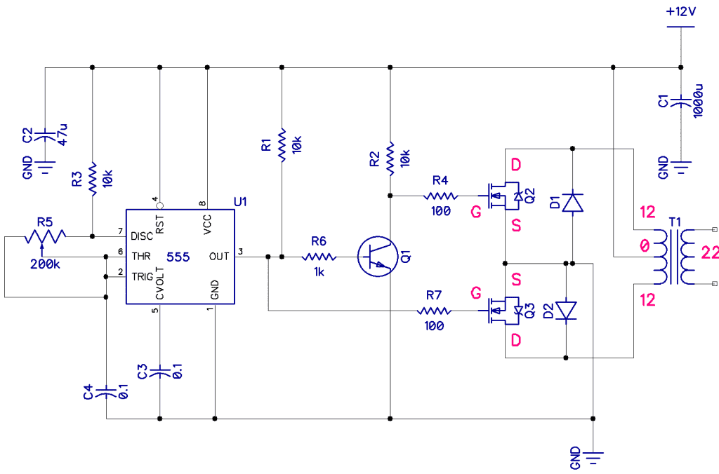
Circuit Working The DC to AC circuit can be separated into three portions namely amplifier, transistor, an oscillator. As the AC supply frequency is 50Hz then a 50Hz oscillator is used. This can be attained by designing an astable multivibrator which generates a 50Hz square wave signal.
DC to AC Converter Circuit projects, 12V to 220VAC
9.1 Basic Block Diagram of dc-ac Inverters Figure 9.1 shows a typical block diagram of a power electronic circuit utilizing a dc-ac inverter with input and output filters used to smooth the output ac signal. The feedback circuit is used to sense the output voltage and compare it with a sinusoidal reference signal as shown in Fig. 9.1.
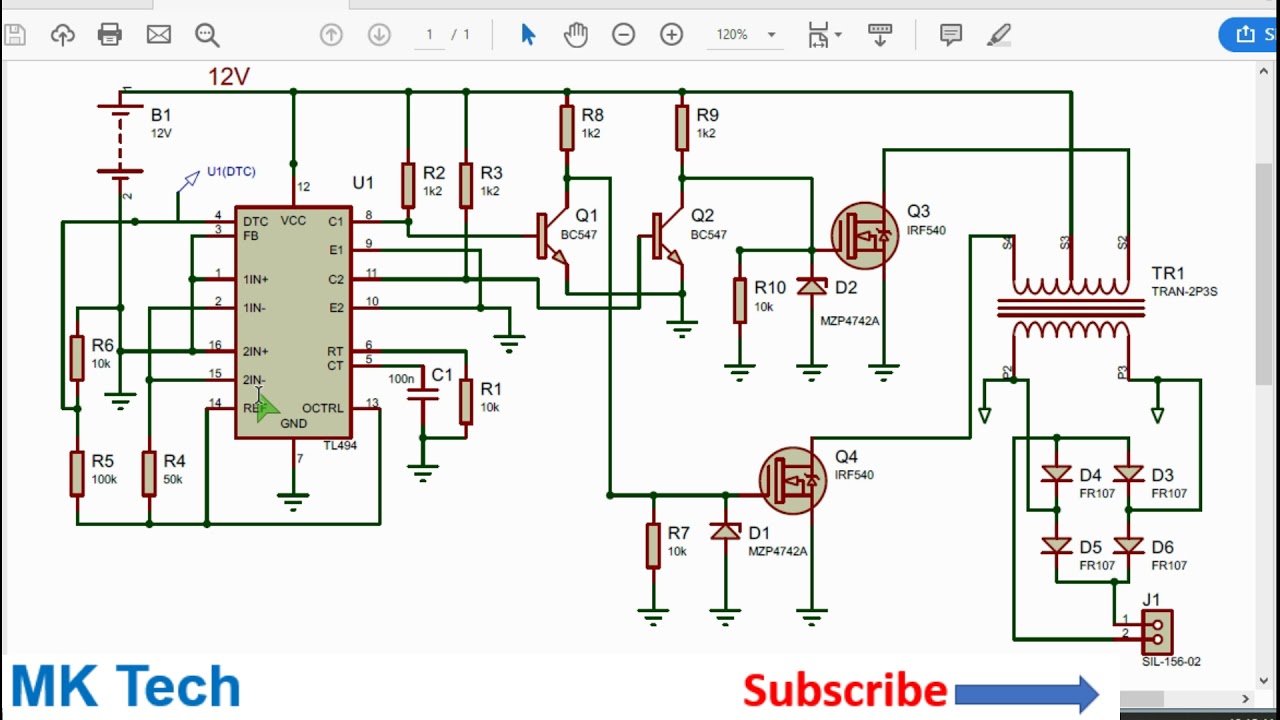
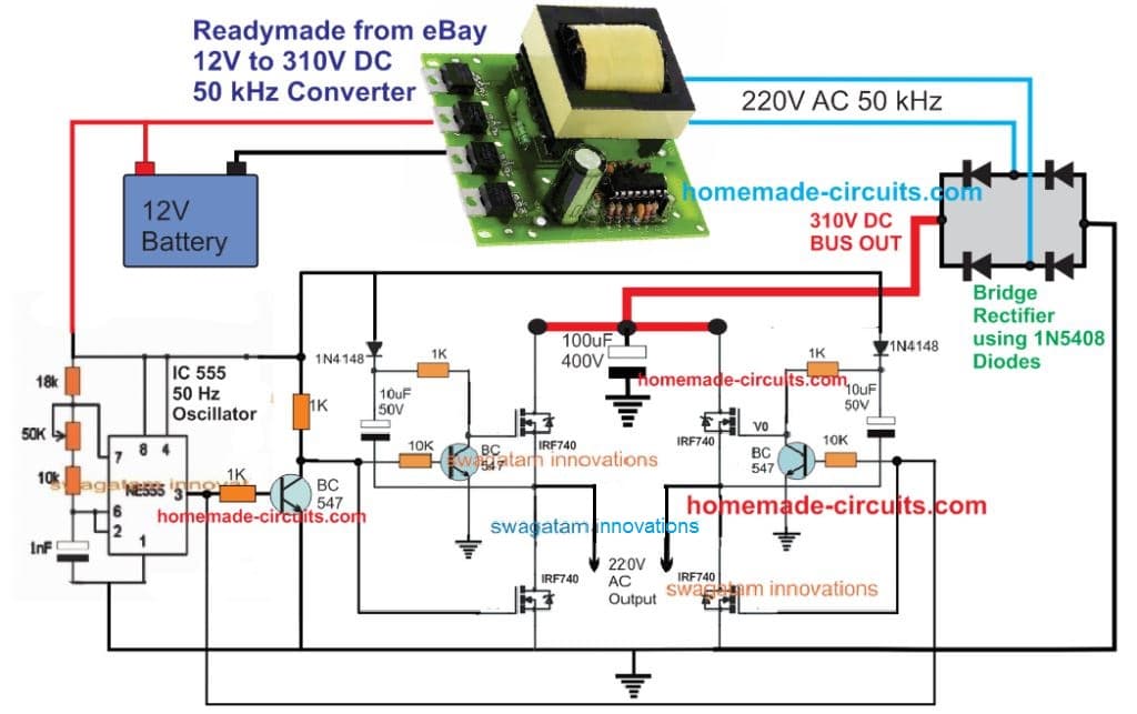
TL494 Inverter Circuit from 12v to 220v DC to AC YouTube
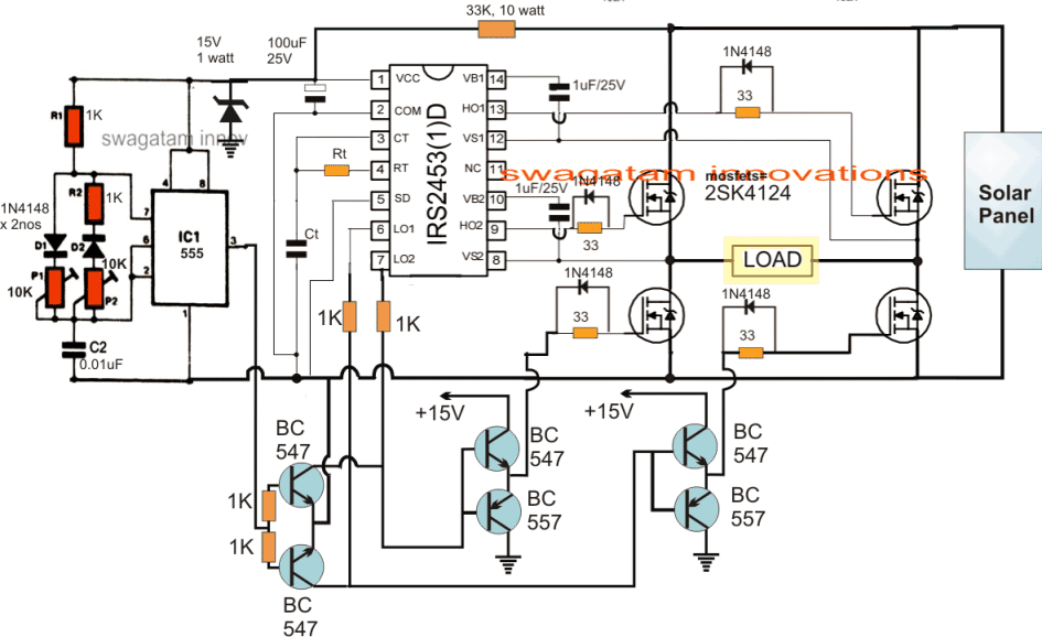
For solar purposes, it's recommended to use a solar DC to AC conversion calculator to determine the proper solar DC to AC conversion factor. DC to AC conversion is also needed for wind turbines or anything involving batteries (e.g., an electric car). And pure sine wave inverters are among the best choices for converting solar power into AC power.
Inverter Ac Pcb Circuit Diagram Pdf
The electrical circuits that transform Direct current (DC) input into Alternating current (AC) output are known as DC-to-AC Converters or Inverters. They are used in power electronic applications where the power input pure 12V, 24V, 48V DC voltage that requires power conversion for an AC output with a certain frequency.

Dc Ac Power Inverter Schematic
Power inverters convert direct current (DC), the power that comes from a car battery, into alternating current (AC), the kind of power supplied to your home and the power larger electronics need to function. What kind of power inverter is the right one for the job? How do you install one?
50 Watts Inverter Circuit ELECTRONICS EVERYDAY
A power inverter circuit is a circuit that converts DC power to AC power. You can make the AC power be any level that you want and to any frequency that you want. The popular values to boost the AC voltage level to is either 110-120V or 220-140V because these are the AC voltages that are used worldwide.

Inverter Power Supply Circuit Diagram
How an Inverter works. April 6, 2020. A n inverter is used to produce an un-interrupted 220V AC or 110V AC (depending on the line voltage of the particular country) supply to the device connected as the load at the output socket. The inverter gives constant AC voltage at its output socket when the AC mains power supply is not available.
How to Make a Simple Inverter Circuit at Home ElectricalCoreCircuits
What is an Inverter? The inverter is an electronic device used to convert Direct Current (DC) into Alternating current (AC). The Alternating Current is a current that consistently changes its magnitude with respect to time. This current flows only in one direction.
How to Build a DC to AC Power Inverter Circuit Basics
1. Inverters.. 4 1.1. Need for an inverter for motor control applications 4 2. Control, commutation, and modulation methods for inverters. 5 3.

220v Ac To 12v Dc Converter Circuit Diagram With Transformer Wiring
The power supply that comes from the outlet in your wall is based on alternating current (AC), where the electricity switches direction around 50-60 times each second (in other words, at a frequency of 50-60 Hz). It can be hard to understand how AC delivers energy when it's constantly changing its mind about where it's going!
DCtoDC AC Inverter Circuit Diagram Expert Circuits
The 1.5V to 220V AC inverter circuit provides a simple and efficient solution for converting low-voltage DC power into higher-voltage AC output. By following the circuit diagram and understanding its working principles, you can build an inverter that suits your power requirements. Remember to take necessary precautions while working with.
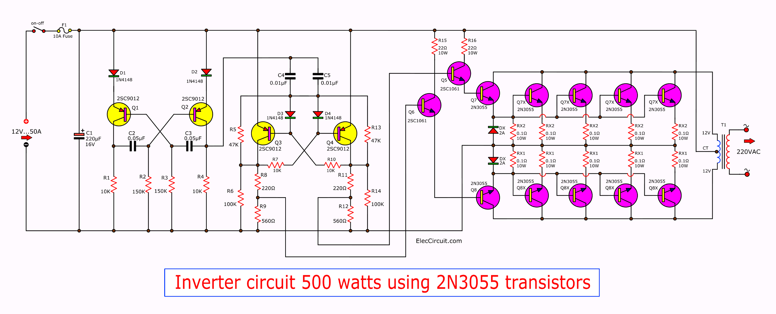
Inverter circuit 500w, 12V to 220V
In another vein, an AC inverter or AC inverter circuit adjusts the compressor speed to control the gas (refrigerant) flow rate, thus, consuming low power and current. 3. Inverter Circuit-Electric motor speed control. In the same vein, they help to adjust the rotation speed of a motor. With a simple inverter, you can control rotation speed.
Power Inverter Circuit Diagram Pdf Wiring Diagram
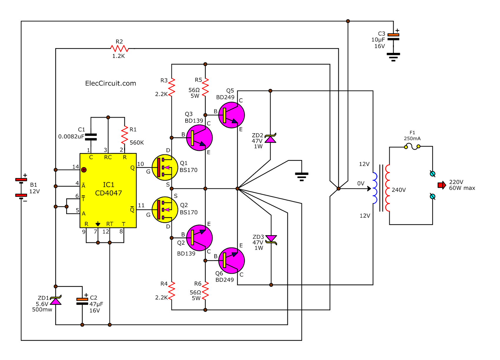
An inverter circuit is used to convert the DC power to AC power. Inverter Circuit are very much helpful to produce high voltage using low voltage DC supply or Battery. DC-DC Converter circuit can also be used but it has certain voltage limitations. The 12V DC to 220V AC inverter circuit is designed using IC CD4047.
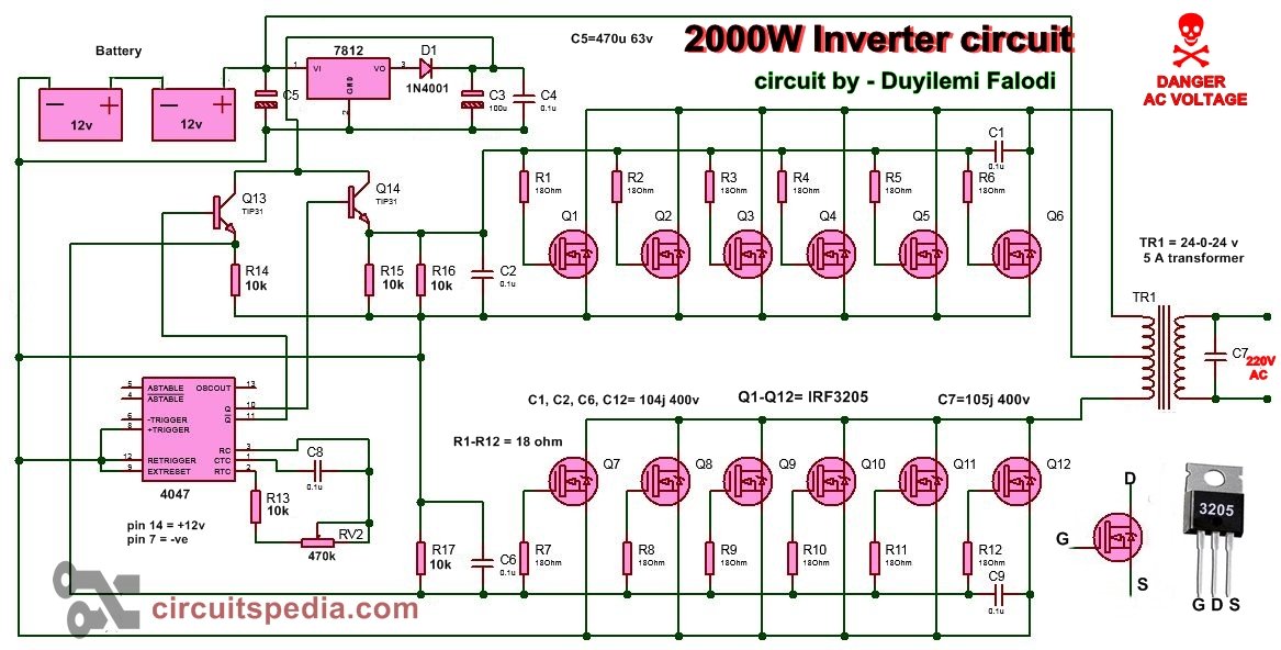
How to build 200W inverter circuit Diagram project
The inverter does not produce any power; the power is provided by the DC source. Figure below shows Basic DC-AC Inverter Block Diagram. A typical power inverter device or circuit requires a relatively stable DC power source capable of supplying enough current for the intended power demands of the system.
5kva Ferrite Core Inverter Circuit Full Working Diagram with
A power inverter, inverter or invertor is a power electronic device or circuitry that changes direct current (DC) to alternating current (AC). [1] The resulting AC frequency obtained depends on the particular device employed. Inverters do the opposite of rectifiers which were originally large electromechanical devices converting AC to DC. [2]
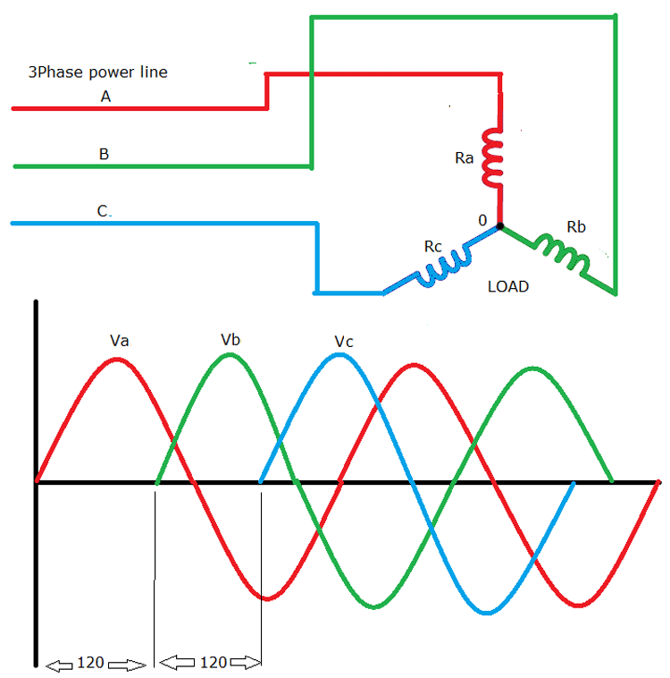
Three Phase Inverter Circuit Diagram 120 Degree and 180 Degree
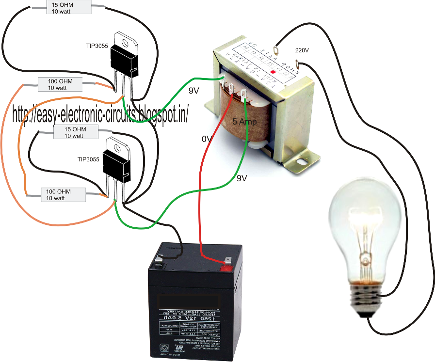
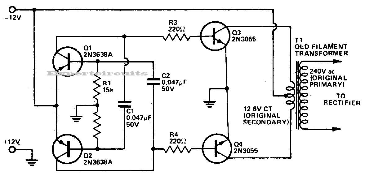
An inverter which uses minimum number of components for converting a 12 V DC to 230 V AC is called a simple inverter. A 12 V lead acid battery is the most standard form of battery which is used for operating such inverters. Let's begin with the most simplest in the list which utilizes a couple of 2N3055 transistors and some resistors.